# 조명 다루기
장면이 3D라는 것은 카메라 때문에 알 수 있지만, 여전히 매우 평평하게 느껴집니다. 이는 모델의 방향에 관계없이 색상이 동일하게 유지되기 때문입니다. 이를 바꾸고 싶다면 장면에 조명을 추가해야 합니다.
현실 세계에서 광원은 광자(photon)를 방출하고, 이 광자들이 여러 번 튕겨 다니다가 우리 눈으로 들어옵니다. 우리가 보는 색은 빛의 원래 색에서 튕기는 동안 잃어버린 에너지를 뺀 것입니다.
컴퓨터 그래픽 세계에서 개별 광자를 모델링하는 것은 터무니없이 계산 비용이 많이 듭니다. 100와트 전구 하나는 초당 약 3.27 x 10^20개의 광자를 방출합니다. 태양의 경우는 상상만 해도 끔찍하죠! 이를 해결하기 위해 우리는 수학을 사용해 속임수를 쓸 것입니다.
몇 가지 옵션에 대해 논의해 봅시다.
# 레이/패스 트레이싱 (Ray/Path Tracing)
이것은 고급 주제이며, 여기서 깊이 다루지는 않을 것입니다. 빛이 실제로 작동하는 방식에 가장 가까운 모델이기 때문에 언급할 필요가 있다고 느꼈습니다. 더 배우고 싶다면 레이 트레이싱 튜토리얼을 확인해 보세요.
# 블린-퐁 모델 (The Blinn-Phong Model)
레이/패스 트레이싱은 대부분의 실시간 애플리케이션에는 계산 비용이 너무 많이 들기 때문에(최근에는 바뀌고 있지만), 퐁 반사 모델 (opens new window)에 기반한 더 효율적이지만 덜 정확한 방법이 자주 사용됩니다. 이 모델은 조명 계산을 주변광(ambient), 난반사광(diffuse), 정반사광(specular) 세 부분으로 나눕니다. 우리는 블린-퐁 모델 (opens new window)을 배울 것이며, 이 모델은 정반사 계산에서 약간의 속임수를 써서 속도를 높입니다.
하지만 그전에, 장면에 조명을 추가해야 합니다.
// lib.rs
#[repr(C)]
#[derive(Debug, Copy, Clone, bytemuck::Pod, bytemuck::Zeroable)]
struct LightUniform {
    position: [f32; 3],
    // 유니폼은 16바이트(4개의 float) 간격 정렬이 필요하므로, 여기에 패딩 필드를 사용해야 합니다.
    _padding: u32,
    color: [f32; 3],
    // 유니폼은 16바이트(4개의 float) 간격 정렬이 필요하므로, 여기에 패딩 필드를 사용해야 합니다.
    _padding2: u32,
}
LightUniform은 공간상의 색을 가진 한 점을 나타냅니다. 우리는 순수한 흰색 빛만 사용할 것이지만, 다른 색의 빛을 사용할 수 있도록 하는 것이 좋습니다.
WGSL 구조체와의 정렬에 대한 경험 법칙은 필드 정렬이 항상 2의 거듭제곱이라는 것입니다. 예를 들어, vec3는 세 개의 float 필드만 가질 수 있어 크기가 12바이트입니다. 정렬은 다음 2의 거듭제곱인 16으로 맞춰집니다. 이는 Rust에서 구조체를 배치할 때 더 신중해야 함을 의미합니다.
일부 개발자들은 정렬 문제를 피하기 위해 vec3 대신 vec4를 사용하기도 합니다. 정렬 규칙에 대한 자세한 내용은 WGSL 사양 (opens new window)에서 확인할 수 있습니다.
이제 빛을 저장하기 위해 또 다른 버퍼를 만들 것입니다.
let light_uniform = LightUniform {
    position: [2.0, 2.0, 2.0],
    _padding: 0,
    color: [1.0, 1.0, 1.0],
    _padding2: 0,
};

 // 빛의 위치를 업데이트할 것이므로 COPY_DST를 사용합니다.
let light_buffer = device.create_buffer_init(
    &wgpu::util::BufferInitDescriptor {
        label: Some("Light VB"),
        contents: bytemuck::cast_slice(&[light_uniform]),
        usage: wgpu::BufferUsages::UNIFORM | wgpu::BufferUsages::COPY_DST,
    }
);
light_uniform과 light_buffer를 State에 추가하는 것을 잊지 마세요. 그 후, 빛을 위한 바인드 그룹 레이아웃과 바인드 그룹을 만들어야 합니다.
let light_bind_group_layout =
    device.create_bind_group_layout(&wgpu::BindGroupLayoutDescriptor {
        entries: &[wgpu::BindGroupLayoutEntry {
            binding: 0,
            visibility: wgpu::ShaderStages::VERTEX | wgpu::ShaderStages::FRAGMENT,
            ty: wgpu::BindingType::Buffer {
                ty: wgpu::BufferBindingType::Uniform,
                has_dynamic_offset: false,
                min_binding_size: None,
            },
            count: None,
        }],
        label: None,
    });

let light_bind_group = device.create_bind_group(&wgpu::BindGroupDescriptor {
    layout: &light_bind_group_layout,
    entries: &[wgpu::BindGroupEntry {
        binding: 0,
        resource: light_buffer.as_entire_binding(),
    }],
    label: None,
});
이것들을 State에 추가하고 render_pipeline_layout도 업데이트하세요.
let render_pipeline_layout = device.create_pipeline_layout(&wgpu::PipelineLayoutDescriptor {
    label: Some("Render Pipeline Layout"), // 레이블 추가
    bind_group_layouts: &[
        &texture_bind_group_layout,
        &camera_bind_group_layout,
        &light_bind_group_layout,
    ],
    push_constant_ranges: &[], // 명시적으로 추가
});
또한 update() 메서드에서 빛의 위치를 업데이트하여 다른 각도에서 객체가 어떻게 보이는지 확인해 봅시다.
// 빛 업데이트
let old_position: cgmath::Vector3<_> = self.light_uniform.position.into();
self.light_uniform.position =
    (cgmath::Quaternion::from_axis_angle((0.0, 1.0, 0.0).into(), cgmath::Deg(1.0))
        * old_position)
        .into();
self.queue.write_buffer(&self.light_buffer, 0, bytemuck::cast_slice(&[self.light_uniform]));
이렇게 하면 빛이 매 프레임마다 원점 주위를 1도씩 회전하게 됩니다.
# 빛 보기
디버깅 목적으로, 장면이 올바르게 보이는지 확인하기 위해 빛이 어디에 있는지 볼 수 있다면 좋을 것입니다. 기존 렌더 파이프라인을 수정하여 빛을 그릴 수도 있지만, 방해가 될 가능성이 높습니다. 대신, 렌더 파이프라인 생성 코드를 create_render_pipeline()이라는 새 함수로 추출할 것입니다.
fn create_render_pipeline(
    device: &wgpu::Device,
    layout: &wgpu::PipelineLayout,
    color_format: wgpu::TextureFormat,
    depth_format: Option<wgpu::TextureFormat>,
    vertex_layouts: &[wgpu::VertexBufferLayout],
    shader: wgpu::ShaderModuleDescriptor,
) -> wgpu::RenderPipeline {
    let shader = device.create_shader_module(shader);

    device.create_render_pipeline(&wgpu::RenderPipelineDescriptor {
        label: Some("Render Pipeline"),
        layout: Some(layout),
        vertex: wgpu::VertexState {
            module: &shader,
            entry_point: "vs_main", // Some() 제거 가능
            buffers: vertex_layouts,
            compilation_options: Default::default(),
        },
        fragment: Some(wgpu::FragmentState {
            module: &shader,
            entry_point: "fs_main", // Some() 제거 가능
            targets: &[Some(wgpu::ColorTargetState {
                format: color_format,
                blend: Some(wgpu::BlendState {
                    alpha: wgpu::BlendComponent::REPLACE,
                    color: wgpu::BlendComponent::REPLACE,
                }),
                write_mask: wgpu::ColorWrites::ALL,
            })],
            compilation_options: Default::default(),
        }),
        primitive: wgpu::PrimitiveState {
            topology: wgpu::PrimitiveTopology::TriangleList,
            strip_index_format: None,
            front_face: wgpu::FrontFace::Ccw,
            cull_mode: Some(wgpu::Face::Back),
            // Fill 이외의 값을 설정하려면 Features::NON_FILL_POLYGON_MODE가 필요합니다.
            polygon_mode: wgpu::PolygonMode::Fill,
            // Features::DEPTH_CLIP_CONTROL가 필요합니다.
            unclipped_depth: false,
            // Features::CONSERVATIVE_RASTERIZATION이 필요합니다.
            conservative: false,
        },
        depth_stencil: depth_format.map(|format| wgpu::DepthStencilState {
            format,
            depth_write_enabled: true,
            depth_compare: wgpu::CompareFunction::Less,
            stencil: wgpu::StencilState::default(),
            bias: wgpu::DepthBiasState::default(),
        }),
        multisample: wgpu::MultisampleState {
            count: 1,
            mask: !0,
            alpha_to_coverage_enabled: false,
        },
        multiview: None,
    })
}
또한 State::new()가 이 함수를 사용하도록 변경해야 합니다.
let render_pipeline = {
    let shader = wgpu::ShaderModuleDescriptor {
        label: Some("Normal Shader"),
        source: wgpu::ShaderSource::Wgsl(include_str!("shader.wgsl").into()),
    };
    create_render_pipeline(
        &device,
        &render_pipeline_layout,
        config.format,
        Some(texture::Texture::DEPTH_FORMAT),
        &[model::ModelVertex::desc(), InstanceRaw::desc()],
        shader,
    )
};
model::DrawModel이 light_bind_group을 사용하도록 수정해야 합니다.
// model.rs
pub trait DrawModel<'a> {
    fn draw_mesh(
        &mut self,
        mesh: &'a Mesh,
        material: &'a Material,
        camera_bind_group: &'a wgpu::BindGroup,
        light_bind_group: &'a wgpu::BindGroup,
    );
    fn draw_mesh_instanced(
        &mut self,
        mesh: &'a Mesh,
        material: &'a Material,
        instances: Range<u32>,
        camera_bind_group: &'a wgpu::BindGroup,
        light_bind_group: &'a wgpu::BindGroup,
    );

    fn draw_model(
        &mut self,
        model: &'a Model,
        camera_bind_group: &'a wgpu::BindGroup,
        light_bind_group: &'a wgpu::BindGroup,
    );
    fn draw_model_instanced(
        &mut self,
        model: &'a Model,
        instances: Range<u32>,
        camera_bind_group: &'a wgpu::BindGroup,
        light_bind_group: &'a wgpu::BindGroup,
    );
}

impl<'a, 'b> DrawModel<'b> for wgpu::RenderPass<'a>
where
    'b: 'a,
{
    fn draw_mesh(
        &mut self,
        mesh: &'b Mesh,
        material: &'b Material,
        camera_bind_group: &'b wgpu::BindGroup,
        light_bind_group: &'b wgpu::BindGroup,
    ) {
        self.draw_mesh_instanced(mesh, material, 0..1, camera_bind_group, light_bind_group);
    }

    fn draw_mesh_instanced(
        &mut self,
        mesh: &'b Mesh,
        material: &'b Material,
        instances: Range<u32>,
        camera_bind_group: &'b wgpu::BindGroup,
        light_bind_group: &'b wgpu::BindGroup,
    ) {
        self.set_vertex_buffer(0, mesh.vertex_buffer.slice(..));
        self.set_index_buffer(mesh.index_buffer.slice(..), wgpu::IndexFormat::Uint32);
        self.set_bind_group(0, &material.bind_group, &[]);
        self.set_bind_group(1, camera_bind_group, &[]);
        self.set_bind_group(2, light_bind_group, &[]);
        self.draw_indexed(0..mesh.num_elements, 0, instances);
    }

    fn draw_model(
        &mut self,
        model: &'b Model,
        camera_bind_group: &'b wgpu::BindGroup,
        light_bind_group: &'b wgpu::BindGroup,
    ) {
        self.draw_model_instanced(model, 0..1, camera_bind_group, light_bind_group);
    }

    fn draw_model_instanced(
        &mut self,
        model: &'b Model,
        instances: Range<u32>,
        camera_bind_group: &'b wgpu::BindGroup,
        light_bind_group: &'b wgpu::BindGroup,
    ) {
        for mesh in &model.meshes {
            let material = &model.materials[mesh.material];
            self.draw_mesh_instanced(mesh, material, instances.clone(), camera_bind_group, light_bind_group);
        }
    }
}
이 작업이 끝나면 빛을 위한 또 다른 렌더 파이프라인을 만들 수 있습니다.
// lib.rs
let light_render_pipeline = {
    let layout = device.create_pipeline_layout(&wgpu::PipelineLayoutDescriptor {
        label: Some("Light Pipeline Layout"),
        bind_group_layouts: &[&camera_bind_group_layout, &light_bind_group_layout],
        push_constant_ranges: &[],
    });
    let shader = wgpu::ShaderModuleDescriptor {
        label: Some("Light Shader"),
        source: wgpu::ShaderSource::Wgsl(include_str!("light.wgsl").into()),
    };
    create_render_pipeline(
        &device,
        &layout,
        config.format,
        Some(texture::Texture::DEPTH_FORMAT),
        &[model::ModelVertex::desc()],
        shader,
    )
};
저는 light_render_pipeline을 위해 별도의 레이아웃을 만들었습니다. 이 파이프라인은 일반 render_pipeline이 필요로 하는 모든 리소스(주로 텍스처)가 필요 없기 때문입니다.
이것이 준비되면, 실제 셰이더를 작성해야 합니다.
// light.wgsl
// 정점 셰이더

struct Camera {
    view_proj: mat4x4<f32>,
}
@group(0) @binding(0)
var<uniform> camera: Camera;

struct Light {
    position: vec3<f32>,
    color: vec3<f32>,
}
@group(1) @binding(0)
var<uniform> light: Light;

struct VertexInput {
    @location(0) position: vec3<f32>,
};

struct VertexOutput {
    @builtin(position) clip_position: vec4<f32>,
    @location(0) color: vec3<f32>,
};

@vertex
fn vs_main(
    model: VertexInput,
) -> VertexOutput {
    let scale = 0.25;
    var out: VertexOutput;
    out.clip_position = camera.view_proj * vec4<f32>(model.position * scale + light.position, 1.0);
    out.color = light.color;
    return out;
}

// 프래그먼트 셰이더

@fragment
fn fs_main(in: VertexOutput) -> @location(0) vec4<f32> {
    return vec4<f32>(in.color, 1.0);
}
이제 render()에서 빛을 그리는 코드를 직접 구현할 수도 있지만, 우리가 개발한 패턴을 유지하기 위해 DrawLight라는 새 트레이트를 만들겠습니다.
// model.rs
pub trait DrawLight<'a> {
    fn draw_light_mesh(
        &mut self,
        mesh: &'a Mesh,
        camera_bind_group: &'a wgpu::BindGroup,
        light_bind_group: &'a wgpu::BindGroup,
    );
    fn draw_light_mesh_instanced(
        &mut self,
        mesh: &'a Mesh,
        instances: Range<u32>,
        camera_bind_group: &'a wgpu::BindGroup,
        light_bind_group: &'a wgpu::BindGroup,
    );

    fn draw_light_model(
        &mut self,
        model: &'a Model,
        camera_bind_group: &'a wgpu::BindGroup,
        light_bind_group: &'a wgpu::BindGroup,
    );
    fn draw_light_model_instanced(
        &mut self,
        model: &'a Model,
        instances: Range<u32>,
        camera_bind_group: &'a wgpu::BindGroup,
        light_bind_group: &'a wgpu::BindGroup,
    );
}

impl<'a, 'b> DrawLight<'b> for wgpu::RenderPass<'a>
where
    'b: 'a,
{
    fn draw_light_mesh(
        &mut self,
        mesh: &'b Mesh,
        camera_bind_group: &'b wgpu::BindGroup,
        light_bind_group: &'b wgpu::BindGroup,
    ) {
        self.draw_light_mesh_instanced(mesh, 0..1, camera_bind_group, light_bind_group);
    }

    fn draw_light_mesh_instanced(
        &mut self,
        mesh: &'b Mesh,
        instances: Range<u32>,
        camera_bind_group: &'b wgpu::BindGroup,
        light_bind_group: &'b wgpu::BindGroup,
    ) {
        self.set_vertex_buffer(0, mesh.vertex_buffer.slice(..));
        self.set_index_buffer(mesh.index_buffer.slice(..), wgpu::IndexFormat::Uint32);
        self.set_bind_group(0, camera_bind_group, &[]);
        self.set_bind_group(1, light_bind_group, &[]);
        self.draw_indexed(0..mesh.num_elements, 0, instances);
    }

    fn draw_light_model(
        &mut self,
        model: &'b Model,
        camera_bind_group: &'b wgpu::BindGroup,
        light_bind_group: &'b wgpu::BindGroup,
    ) {
        self.draw_light_model_instanced(model, 0..1, camera_bind_group, light_bind_group);
    }
    fn draw_light_model_instanced(
        &mut self,
        model: &'b Model,
        instances: Range<u32>,
        camera_bind_group: &'b wgpu::BindGroup,
        light_bind_group: &'b wgpu::BindGroup,
    ) {
        for mesh in &model.meshes {
            self.draw_light_mesh_instanced(mesh, instances.clone(), camera_bind_group, light_bind_group);
        }
    }
}
마지막으로, 렌더 패스에 빛 렌더링을 추가하고 싶습니다.
impl State {
    // ...
   fn render(&mut self) -> Result<(), wgpu::SurfaceError> {
        // ...
        render_pass.set_vertex_buffer(1, self.instance_buffer.slice(..));

        // 드로잉 트레이트를 사용합니다.
        use crate::model::{DrawModel, DrawLight}; // DrawLight 추가!

        // 빛을 먼저 그립니다.
        render_pass.set_pipeline(&self.light_render_pipeline); // 새로운 내용!
        render_pass.draw_light_model(
            &self.obj_model,
            &self.camera_bind_group,
            &self.light_bind_group,
        ); // 새로운 내용!

        // 그 다음 객체를 그립니다.
        render_pass.set_pipeline(&self.render_pipeline);
        render_pass.draw_model_instanced(
            &self.obj_model,
            0..self.instances.len() as u32,
            &self.camera_bind_group,
            &self.light_bind_group, // 새로운 내용!
        );
        // ...
    }
}
이 모든 것을 마치면 다음과 같은 결과물을 얻게 될 것입니다.
# 주변광 (Ambient Lighting)
빛은 우리 눈에 들어오기 전에 주변에서 반사되는 경향이 있습니다. 그림자가 진 곳도 볼 수 있는 이유가 바로 이것입니다. 이 상호작용을 모델링하는 것은 계산 비용이 많이 들기 때문에, 우리는 속임수를 쓸 것입니다. 장면의 다른 부분에서 반사된 빛이 우리 객체를 비추는 것에 대한 주변광 값을 정의합니다.
주변광 부분은 빛의 색과 객체의 색을 기반으로 합니다. 우리는 이미 light_bind_group을 추가했으므로, 셰이더에서 사용하기만 하면 됩니다. shader.wgsl에서 텍스처 유니폼 아래에 다음을 추가하세요.
struct Light {
    position: vec3<f32>,
    color: vec3<f32>,
}
@group(2) @binding(0)
var<uniform> light: Light;
그런 다음, 주변광 색상 값을 계산하고 사용하도록 메인 셰이더 코드를 업데이트해야 합니다.
@fragment
fn fs_main(in: VertexOutput) -> @location(0) vec4<f32> {
    let object_color: vec4<f32> = textureSample(t_diffuse, s_diffuse, in.tex_coords);

    // 주변광은 많이 필요 없으므로 0.1이면 충분합니다.
    let ambient_strength = 0.1;
    let ambient_color = light.color * ambient_strength;

    let result = ambient_color * object_color.xyz;

    return vec4<f32>(result, object_color.a);
}
그러면 다음과 같은 결과물을 얻게 될 것입니다.
# 난반사광 (Diffuse Lighting)
우리 모델에 포함되었던 법선 벡터(normal vector)를 기억하시나요? 드디어 그것들을 사용할 것입니다. 법선은 표면이 향하는 방향을 나타냅니다. 프래그먼트의 법선과 광원을 가리키는 벡터를 비교하여 해당 프래그먼트가 얼마나 밝거나 어두워야 하는지에 대한 값을 얻습니다. 두 벡터를 내적(dot product)하여 그들 사이의 각도의 코사인 값을 얻습니다.
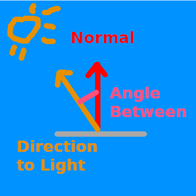
법선과 빛 벡터의 내적이 1.0이면, 현재 프래그먼트가 광원과 직접 일직선상에 있어 빛의 최대 강도를 받는다는 의미입니다. 값이 0.0 이하면 표면이 빛에 수직이거나 등을 돌리고 있어 어둡다는 의미입니다.
이제 shader.wgsl에 법선 벡터를 가져와야 합니다.
struct VertexInput {
    @location(0) position: vec3<f32>,
    @location(1) tex_coords: vec2<f32>,
    @location(2) normal: vec3<f32>, // 새로운 내용!
};
또한 그 값과 정점의 위치를 프래그먼트 셰이더로 전달하고 싶을 것입니다.
struct VertexOutput {
    @builtin(position) clip_position: vec4<f32>,
    @location(0) tex_coords: vec2<f32>,
    @location(1) world_normal: vec3<f32>,
    @location(2) world_position: vec3<f32>,
};
지금은 법선을 그대로 전달하겠습니다. 이것은 잘못된 방법이지만, 나중에 수정할 것입니다.
@vertex
fn vs_main(
    model: VertexInput,
    instance: InstanceInput,
) -> VertexOutput {
    let model_matrix = mat4x4<f32>(
        instance.model_matrix_0,
        instance.model_matrix_1,
        instance.model_matrix_2,
        instance.model_matrix_3,
    );
    var out: VertexOutput;
    out.tex_coords = model.tex_coords;
    out.world_normal = model.normal;
    let world_position: vec4<f32> = model_matrix * vec4<f32>(model.position, 1.0);
    out.world_position = world_position.xyz;
    out.clip_position = camera.view_proj * world_position;
    return out;
}
이제 실제 계산을 할 수 있습니다. ambient_color 계산 아래, result 위에 다음을 추가하세요.
let light_dir = normalize(light.position - in.world_position);

let diffuse_strength = max(dot(in.world_normal, light_dir), 0.0);
let diffuse_color = light.color * diffuse_strength;
이제 result에 diffuse_color를 포함시킬 수 있습니다.
let result = (ambient_color + diffuse_color) * object_color.xyz;
그러면 다음과 같은 결과물을 얻게 됩니다.
# 법선 행렬 (The normal matrix)
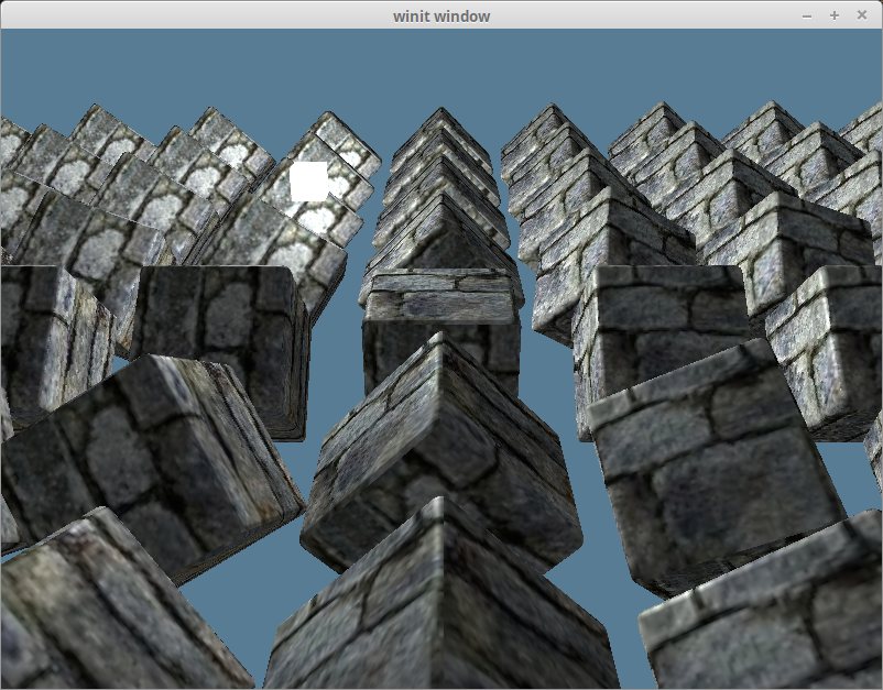
정점 법선을 프래그먼트 셰이더로 직접 전달하는 것이 잘못되었다고 말했던 것을 기억하시나요? y축으로 180도 회전된 큐브 하나만 남기고 장면에서 모든 큐브를 제거하여 이를 탐구해 봅시다.
const NUM_INSTANCES_PER_ROW: u32 = 1;

// 인스턴스를 생성하는 루프 안에서
let rotation = cgmath::Quaternion::from_axis_angle((0.0, 1.0, 0.0).into(), cgmath::Deg(180.0));
또한 조명 result에서 ambient_color를 제거할 것입니다.
let result = (diffuse_color) * object_color.xyz;
그러면 다음과 같이 보일 것입니다.
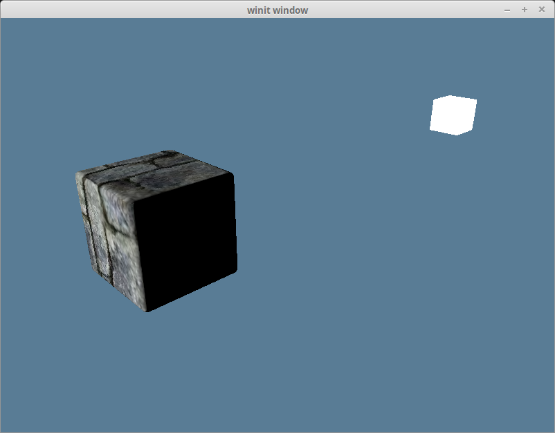
빛이 큐브의 잘못된 면을 비추고 있으므로 이는 명백히 잘못되었습니다. 이는 법선을 객체와 함께 회전시키지 않았기 때문입니다. 객체가 어떤 방향을 향하든 법선은 항상 같은 방향을 향하게 됩니다.

법선을 올바른 방향으로 변환하기 위해 모델 행렬을 사용해야 합니다. 하지만 회전 데이터만 원합니다. 법선은 방향을 나타내며 계산 내내 단위 벡터여야 합니다. 법선 행렬(normal matrix)이라는 것을 사용하여 법선을 올바른 방향으로 만들 수 있습니다.
정점 셰이더에서 법선 행렬을 계산할 수도 있지만, 이는 model_matrix를 역행렬로 만들어야 하고 WGSL에는 실제로 역행렬 함수가 없습니다. 우리 스스로 코드를 짜야 합니다. 게다가 행렬의 역행렬을 계산하는 것은 특히 모든 정점에 대해 그 계산을 수행하는 것은 매우 비용이 많이 듭니다.
대신, InstanceRaw에 normal 행렬 필드를 추가할 것입니다. 모델 행렬을 역행렬로 만드는 대신, 인스턴스의 회전을 사용하여 Matrix3를 만들 것입니다.
행렬의 회전 성분만 필요하므로 Matrix4 대신 Matrix3를 사용하고 있습니다.
#[repr(C)]
#[derive(Debug, Copy, Clone, bytemuck::Pod, bytemuck::Zeroable)]
#[allow(dead_code)]
struct InstanceRaw {
    model: [[f32; 4]; 4],
    normal: [[f32; 3]; 3],
}

impl InstanceRaw { // `model::Vertex` 트레이트 구현을 직접 impl 블록으로 변경
    fn desc() -> wgpu::VertexBufferLayout<'static> {
        use std::mem;
        wgpu::VertexBufferLayout {
            array_stride: mem::size_of::<InstanceRaw>() as wgpu::BufferAddress,
            // Vertex의 step mode에서 Instance로 전환해야 합니다.
            // 이는 셰이더가 새 인스턴스 처리를 시작할 때만
            // 다음 인스턴스를 사용하도록 변경됨을 의미합니다.
            step_mode: wgpu::VertexStepMode::Instance,
            attributes: &[
                wgpu::VertexAttribute {
                    offset: 0,
                    // 정점 셰이더는 이제 location 0과 1만 사용하지만, 나중 튜토리얼에서는
                    // Vertex에 2, 3, 4를 사용할 것입니다. 나중에 충돌하지 않도록 슬롯 5에서 시작하겠습니다.
                    shader_location: 5,
                    format: wgpu::VertexFormat::Float32x4,
                },
                // mat4는 기술적으로 4개의 vec4이므로 4개의 정점 슬롯을 차지합니다.
                // 각 vec4에 대해 슬롯을 정의해야 합니다. 코드에서 이를 직접 할 필요는 없습니다.
                wgpu::VertexAttribute {
                    offset: mem::size_of::<[f32; 4]>() as wgpu::BufferAddress,
                    shader_location: 6,
                    format: wgpu::VertexFormat::Float32x4,
                },
                wgpu::VertexAttribute {
                    offset: mem::size_of::<[f32; 8]>() as wgpu::BufferAddress,
                    shader_location: 7,
                    format: wgpu::VertexFormat::Float32x4,
                },
                wgpu::VertexAttribute {
                    offset: mem::size_of::<[f32; 12]>() as wgpu::BufferAddress,
                    shader_location: 8,
                    format: wgpu::VertexFormat::Float32x4,
                },
                // 새로운 내용!
                wgpu::VertexAttribute {
                    offset: mem::size_of::<[f32; 16]>() as wgpu::BufferAddress,
                    shader_location: 9,
                    format: wgpu::VertexFormat::Float32x3,
                },
                wgpu::VertexAttribute {
                    offset: mem::size_of::<[f32; 19]>() as wgpu::BufferAddress,
                    shader_location: 10,
                    format: wgpu::VertexFormat::Float32x3,
                },
                wgpu::VertexAttribute {
                    offset: mem::size_of::<[f32; 22]>() as wgpu::BufferAddress,
                    shader_location: 11,
                    format: wgpu::VertexFormat::Float32x3,
                },
            ],
        }
    }
}
법선 행렬을 생성하도록 Instance를 수정해야 합니다.
struct Instance {
    position: cgmath::Vector3<f32>,
    rotation: cgmath::Quaternion<f32>,
}

impl Instance {
    fn to_raw(&self) -> InstanceRaw {
        let model =
            cgmath::Matrix4::from_translation(self.position) * cgmath::Matrix4::from(self.rotation);
        InstanceRaw {
            model: model.into(),
            // 새로운 내용!
            normal: cgmath::Matrix3::from(self.rotation).into(),
        }
    }
}
이제 정점 셰이더에서 법선 행렬을 재구성해야 합니다.
struct InstanceInput {
    @location(5) model_matrix_0: vec4<f32>,
    @location(6) model_matrix_1: vec4<f32>,
    @location(7) model_matrix_2: vec4<f32>,
    @location(8) model_matrix_3: vec4<f32>,
    // 새로운 내용!
    @location(9) normal_matrix_0: vec3<f32>,
    @location(10) normal_matrix_1: vec3<f32>,
    @location(11) normal_matrix_2: vec3<f32>,
};

struct VertexOutput {
    @builtin(position) clip_position: vec4<f32>,
    @location(0) tex_coords: vec2<f32>,
    @location(1) world_normal: vec3<f32>,
    @location(2) world_position: vec3<f32>,
};

@vertex
fn vs_main(
    model: VertexInput,
    instance: InstanceInput,
) -> VertexOutput {
    let model_matrix = mat4x4<f32>(
        instance.model_matrix_0,
        instance.model_matrix_1,
        instance.model_matrix_2,
        instance.model_matrix_3,
    );
    // 새로운 내용!
    let normal_matrix = mat3x3<f32>(
        instance.normal_matrix_0,
        instance.normal_matrix_1,
        instance.normal_matrix_2,
    );
    var out: VertexOutput;
    out.tex_coords = model.tex_coords;
    out.world_normal = normal_matrix * model.normal; // 수정된 내용!
    let world_position: vec4<f32> = model_matrix * vec4<f32>(model.position, 1.0);
    out.world_position = world_position.xyz;
    out.clip_position = camera.view_proj * world_position;
    return out;
}
저는 현재 월드 공간(world space) (opens new window)에서 작업을 하고 있습니다. 뷰 공간(view-space), 즉 시야 공간(eye-space)에서 작업하는 것이 더 표준적입니다. 객체가 원점에서 멀어질수록 조명 문제가 발생할 수 있기 때문입니다. 뷰 공간을 사용하려면 뷰 행렬로 인한 회전도 포함해야 합니다. 또한 카메라가 움직일 때 계산이 틀어지는 것을 막기 위해 view_matrix * model_matrix * light_position과 같은 방식으로 빛의 위치도 변환해야 합니다.
뷰 공간을 사용하면 장점이 있습니다. 가장 큰 장점은 거대한 월드가 있을 때 모델 공간에서 조명 및 기타 계산을 수행하면 부동 소수점 정밀도가 큰 숫자에서 저하되어 문제가 발생할 수 있다는 것입니다. 뷰 공간은 카메라를 원점에 유지하여 모든 계산이 더 작은 숫자를 사용하게 합니다. 실제 조명 수학은 동일하게 유지되지만, 설정이 조금 더 필요합니다.
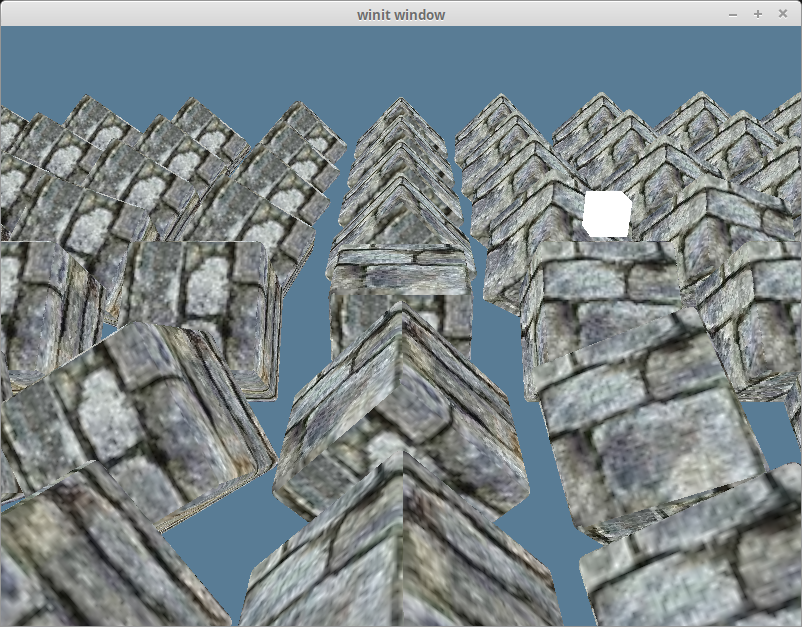
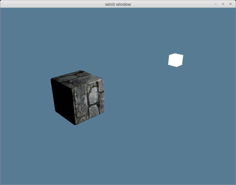
이 변경으로 이제 조명이 올바르게 보입니다.
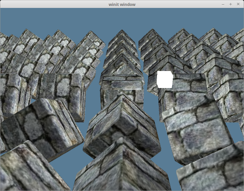
다른 객체들을 다시 가져오고 주변광을 추가하면 다음과 같습니다.
모델 행렬이 항상 객체에 균일한 스케일링(uniform scaling)을 적용한다고 보장할 수 있다면, 모델 행렬만 사용해도 괜찮습니다. Github 사용자 @julhe가 저에게 이 트릭을 알려주었습니다.
out.world_normal = (model_matrix * vec4<f32>(model.normal, 0.0)).xyz;
이는 4x4 행렬에 w 성분이 0인 벡터를 곱하면 회전과 스케일링만 벡터에 적용된다는 사실을 이용합니다. 하지만 법선은 계산이 작동하려면 단위 길이여야 하므로 이 벡터를 정규화해야 합니다.
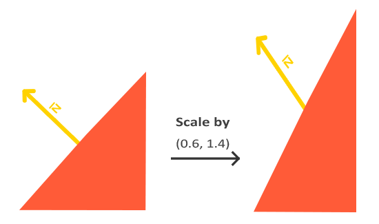
이 방법이 작동하려면 스케일링 인자가 반드시 균일해야 합니다. 그렇지 않으면 다음 이미지에서 볼 수 있듯이 결과 법선이 왜곡됩니다.
# 정반사광 (Specular Lighting)
정반사광은 특정 각도에서 볼 때 객체에 나타나는 하이라이트를 설명합니다. 자동차를 본 적이 있다면, 매우 밝게 빛나는 부분입니다. 기본적으로 일부 빛이 거울처럼 표면에서 반사될 수 있습니다. 하이라이트의 위치는 보는 각도에 따라 달라집니다.

이것은 시야각에 상대적이기 때문에, 카메라의 위치를 프래그먼트 셰이더와 정점 셰이더 모두에 전달해야 합니다.
struct Camera {
    view_pos: vec4<f32>,
    view_proj: mat4x4<f32>,
}
@group(1) @binding(0)
var<uniform> camera: Camera;
light.wgsl의 Camera 구조체도 업데이트하는 것을 잊지 마세요. Rust의 CameraUniform 구조체와 일치하지 않으면 빛이 잘못 렌더링됩니다.
CameraUniform 구조체도 업데이트해야 합니다.
// lib.rs
#[repr(C)]
#[derive(Copy, Clone, bytemuck::Pod, bytemuck::Zeroable)]
struct CameraUniform {
    view_position: [f32; 4],
    view_proj: [[f32; 4]; 4],
}

impl CameraUniform {
    fn new() -> Self {
        Self {
            view_position: [0.0; 4],
            view_proj: cgmath::Matrix4::identity().into(),
        }
    }

    fn update_view_proj(&mut self, camera: &Camera, proj: &Projection) { // proj 추가
        // 유니폼의 16바이트 간격 요구사항 때문에 Vector4를 사용합니다.
        self.view_position = camera.position.to_homogeneous().into();
        self.view_proj = (proj.calc_matrix() * camera.calc_matrix()).into();
    }
}
이제 프래그먼트 셰이더에서 유니폼을 사용하고 싶으므로, 가시성을 변경해야 합니다.
// lib.rs
let camera_bind_group_layout = device.create_bind_group_layout(&wgpu::BindGroupLayoutDescriptor {
    entries: &[
        wgpu::BindGroupLayoutEntry { // wgpu::BindGroupLayoutBinding -> wgpu::BindGroupLayoutEntry
            binding: 0,
            visibility: wgpu::ShaderStages::VERTEX | wgpu::ShaderStages::FRAGMENT, // 수정됨!
            ty: wgpu::BindingType::Buffer {
                ty: wgpu::BufferBindingType::Uniform,
                has_dynamic_offset: false,
                min_binding_size: None,
            },
            count: None,
        },
    ],
    label: Some("camera_bind_group_layout"), // 레이블 추가
});
프래그먼트 위치에서 카메라까지의 방향을 얻고 그것을 법선과 함께 사용하여 reflect_dir을 계산할 것입니다.
// shader.wgsl
// 프래그먼트 셰이더 안에서...
let view_dir = normalize(camera.view_pos.xyz - in.world_position);
let reflect_dir = reflect(-light_dir, in.world_normal);
그런 다음, 내적을 사용하여 specular_strength를 계산하고 그것을 사용하여 specular_color를 계산합니다.
let specular_strength = pow(max(dot(view_dir, reflect_dir), 0.0), 32.0);
let specular_color = specular_strength * light.color;
마지막으로 결과에 그것을 더합니다.
let result = (ambient_color + diffuse_color + specular_color) * object_color.xyz;
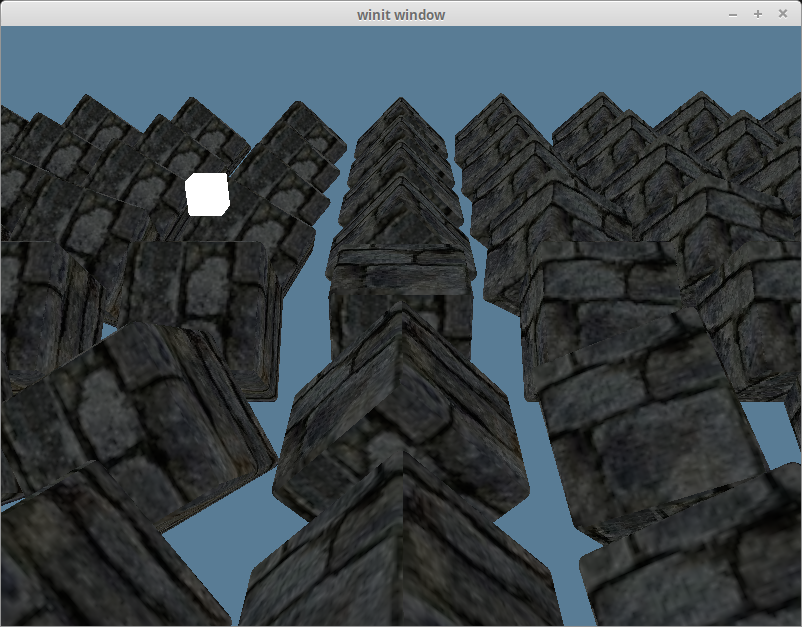
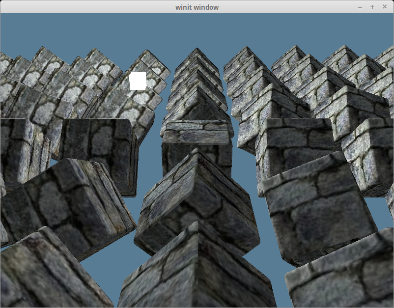
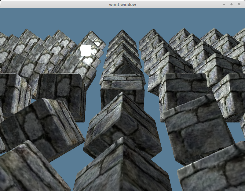
그러면 다음과 같은 결과물을 얻게 될 것입니다.
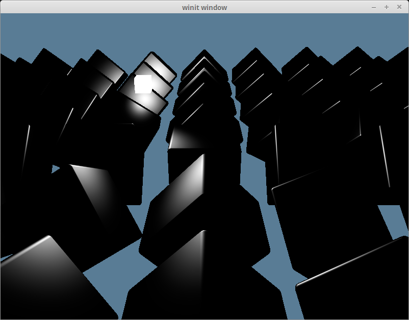
specular_color만 따로 보면 다음과 같습니다.
# 하프 디렉션 (The half direction)
지금까지 우리는 실제로 블린-퐁의 퐁 부분만 구현했습니다. 퐁 반사 모델은 잘 작동하지만, 특정 상황에서는 (opens new window) 문제가 발생할 수 있습니다. 블린-퐁의 블린 부분은 view_dir과 light_dir을 더하고 그 결과를 정규화한 다음, 그것과 normal의 내적을 사용하면 reflect_dir을 사용할 때 발생했던 문제 없이 거의 동일한 결과를 얻을 수 있다는 깨달음에서 비롯됩니다.
let view_dir = normalize(camera.view_pos.xyz - in.world_position);
let half_dir = normalize(view_dir + light_dir);

let specular_strength = pow(max(dot(in.world_normal, half_dir), 0.0), 32.0);
차이를 구별하기는 어렵지만, 결과는 다음과 같습니다.